Platform for Simulated Helicopter Motion
3DOF (Pitch, Roll, & Yaw)
![]()
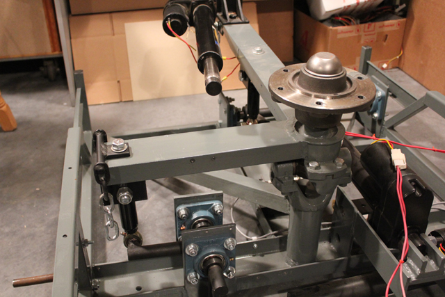
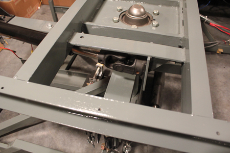
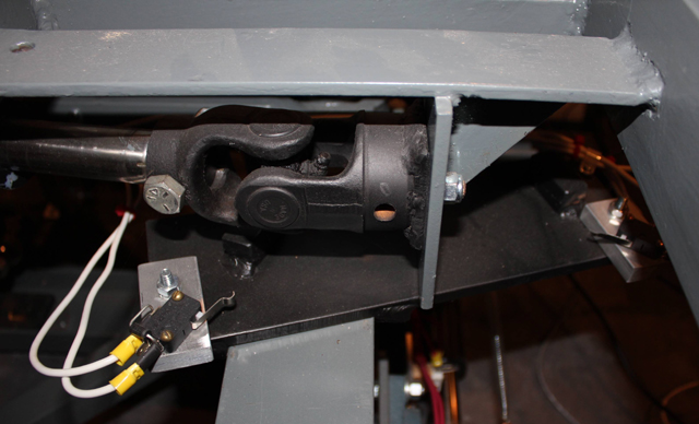
The universal joint allows movement for "pitch and roll" axis positions.
On top is the rotating hub which allows for the "yaw" axis (tail rotor control) movement.
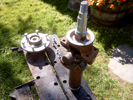
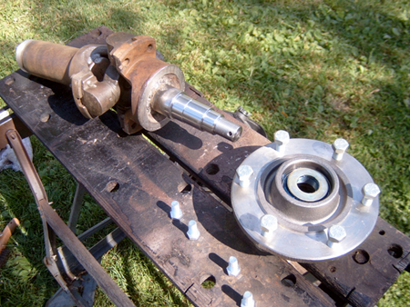
Heavy truck universal joint with the hub's spindle welded in the top center of the universal joint flange.
The universal joint came from a vehicle wrecking yard, the heavy duty hub and spindle from a farm implement supply.
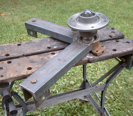
Pitch and roll control arms (3" steel channel) welded to top universal joint flange.
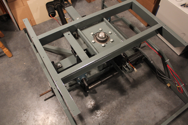
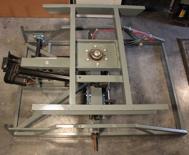
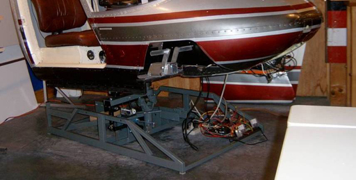
The simulator sits on this welded steel frame, which bolts to the rotating hub.
Yaw Axis
(Left Photo) An offset mounting bracket for the yaw axis actuator was fabricated and bolted to the extended pitch control arm.
(Right Photo) The shaft of the linear actuator is attached to the pivoting yaw frame with a small universal joint.
Pitch Axis
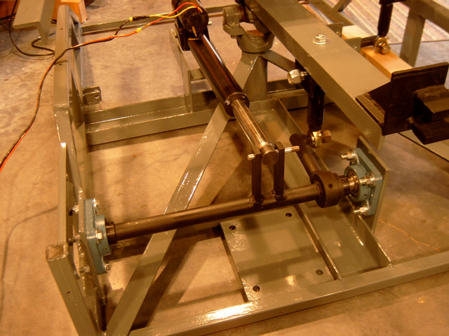
In order to mount the actuators inside the frame, ball bearing equipped jackshafts were installed, to accommodate the the stroke length of the actuators and redirect the output direction from horizontal to vertical. This jackshaft connects the pitch axis control arm to the linear actuator.
Roll Axis
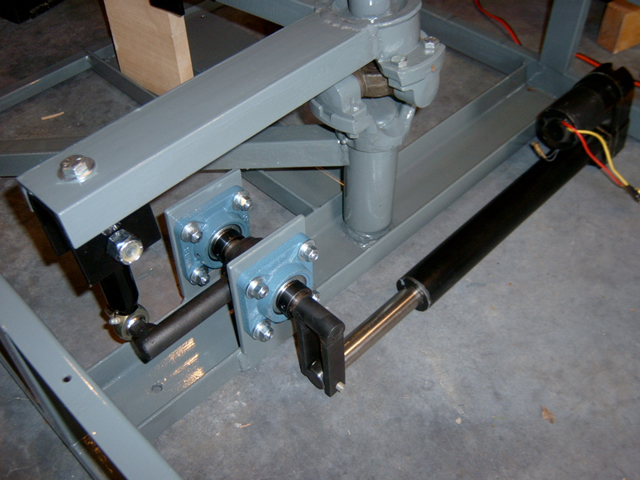
This jackshaft connects the roll axis control arm to the linear actuator.
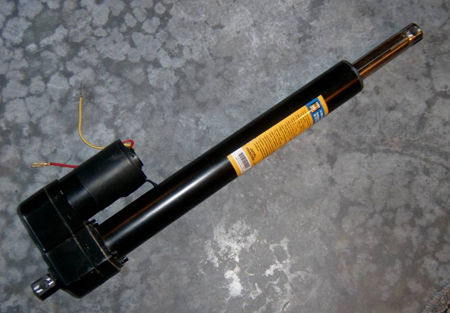
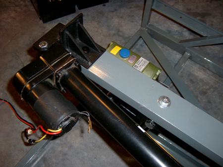
The 12 volt DC linear actuator has a 10:1 gear ratio, ball bearing screw, 12" stroke and can move 500 lbs. These actuators are not extremely fast, but when you consider they are sitting under a Bell 206 and if the helicopter is operated appropriately, they seem to provide enough speed and power to suit the conditions.
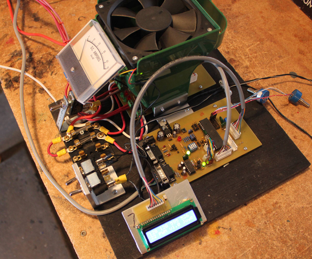
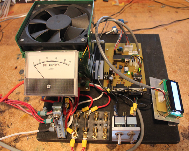
This board contains the DC motor controllers.
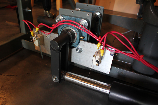
Limit Switches
Safety limit switches control excessive actuator stroke travel to prevent damage to moving simulator components, if a computer or motor controller malfunction should occur. If the jackshaft lever reaches one of the switches, the limit switch lever is pressed, cutting the power to the motor. A diode is used across the terminals of the switch, which allows the current to flow in the reverse direction, so that the motor may be restarted and moved away from that limit.
Roll axis
Pitch axis
Yaw axis
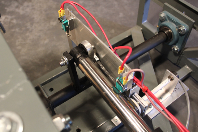
Axis Position Sensors
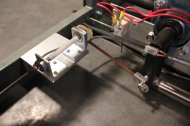
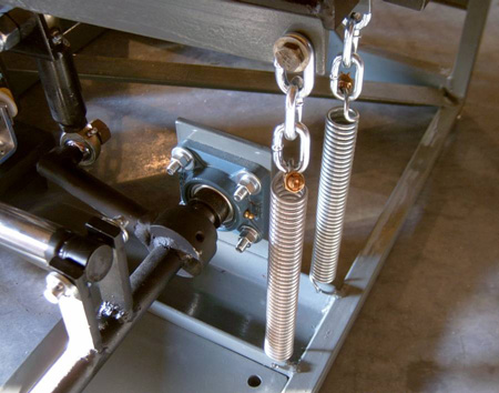
Potentiometers keep track of where each axis position is at any given time and provide feedback to the motor controller. The potentiometers are driven with a ball bearing supported plastic timing pulley. A short length of timing belt, which has one end attached to the axis control arm, drives the pulley. A tensioning spring on the other end of the belt keeps it tight. This system helps prevent any "backlash" that might occur with other types of gearing, or lever type attachment points to the potentiometers.
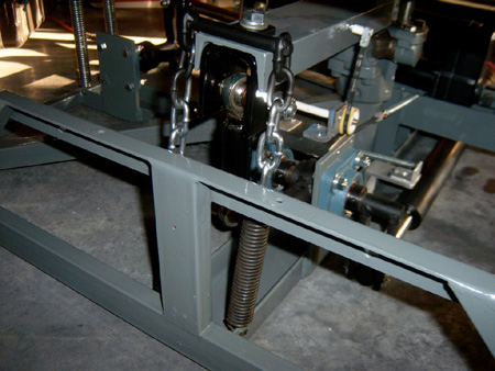
Balancing is critical to this type of design, to help allow the motors to handle the extreme platform positions.These helper springs serve two functions. They prevent any "slack or flop" in the drive train when the platform passes over the center position and they help take the load off the motors when the platform reaches the extreme positions.