Bell JetRanger
![]()
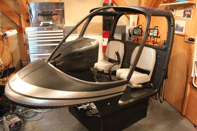
This Bell 206 simulator is equipped with dual flight controls and could be used for teaching general helicopter procedures, instrument navigation, Bell 206 turbine transition, emergency procedures, including some limited IFR training. It has a functioning overhead panel and main instrument panel with associated switches and rotary encoders for navigational instruments. Accurate representations of gauges displaying proper engine and transmission oil pressures, temperatures, TOT, electrical voltage loads, fuel load, fore and aft fuel pump pressures and differentials are simulated, as well as "by the book" Bell 206B start up, run up, flight, and shutdown procedures.
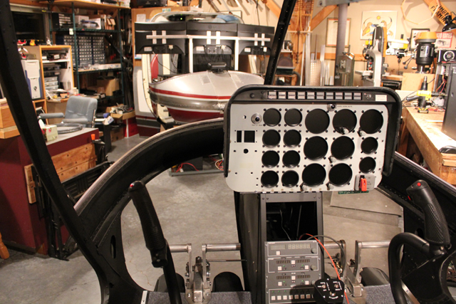
The gauges and instruments are displayed by a single LCD monitor behind the main panel overlay.
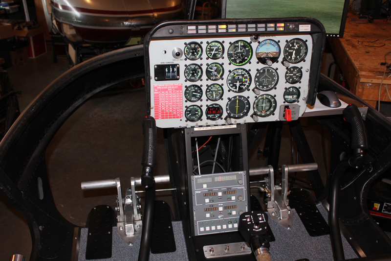
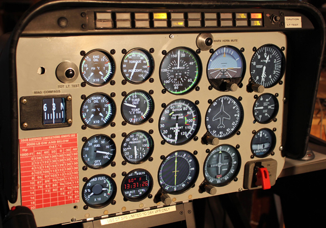
Rotary switch encoders are used to control the attitude bar, altimeter, gyro, ADF, and VOR instruments.
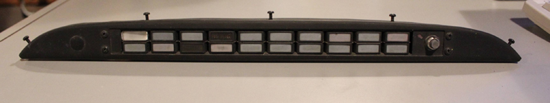
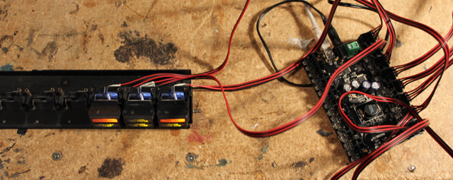
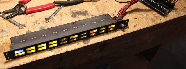
The Bell 206 annunciator panel was retrofitted with LEDs and a PhidgetLED-64.
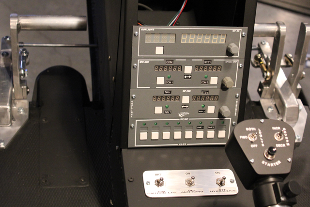
Goflight radios and switches
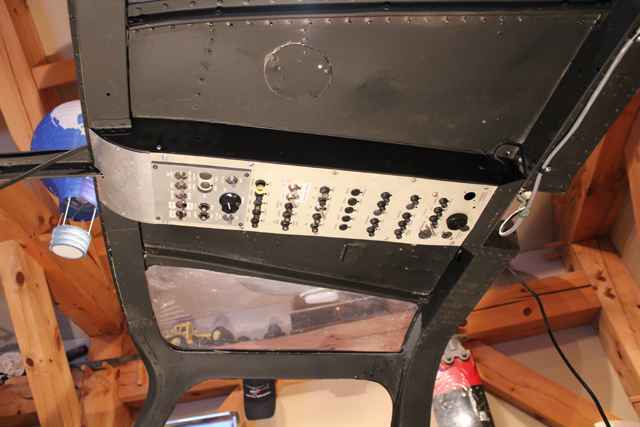
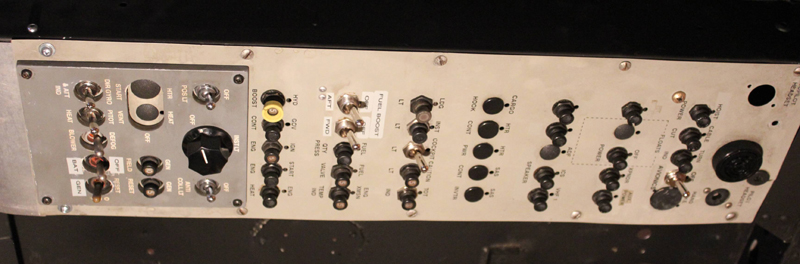
Bell 206 overhead panel
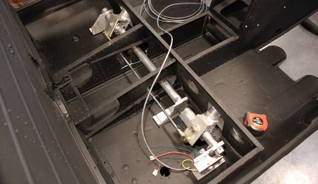
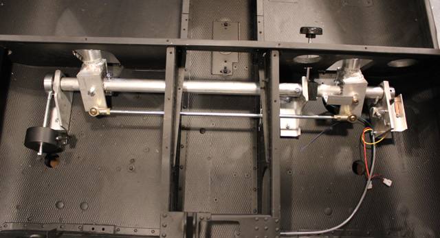
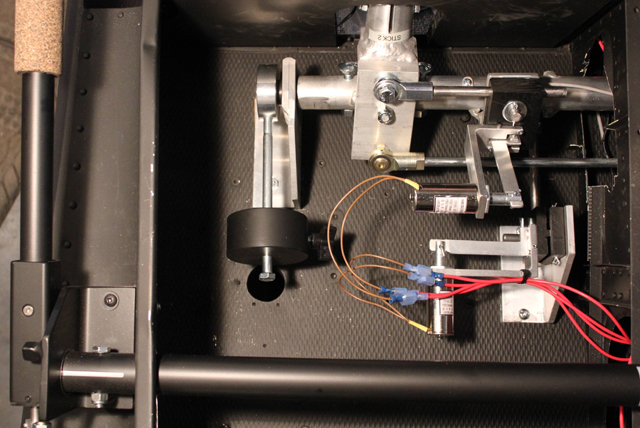
This dual control cyclic controller is fabricated from 6061-T6 aluminum and incorporates precision ball bearings on each axis for strength and smoothness. The controller connects to the sim computer via two Honeywell SS495 Hall effect sensors and a 12-bit USB joystick interface.
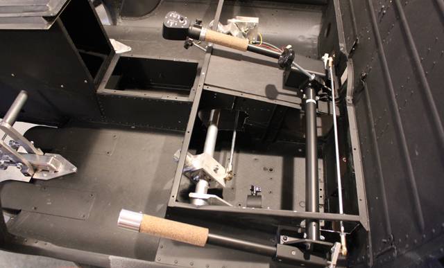
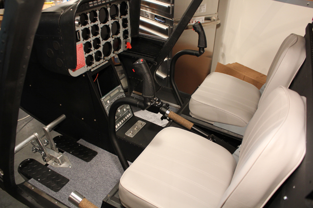
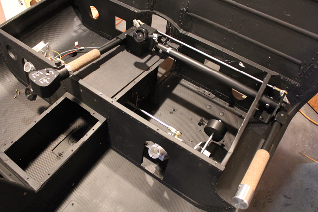
Shown here is the dual control collective. The main and secondary collective levers have synchronized throttle twist grips. The main throttle grip has a spring loaded mechanical idle release button and a detent position that interacts with the release button for realistic simulated Bell 206 startup and shutdown procedures. Throttle grip and blade pitch lever positions are monitored with Honeywell SS495 Hall effect sensors. The collective has a Delrin friction control brake with accessible knob for the pilot.
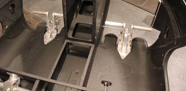
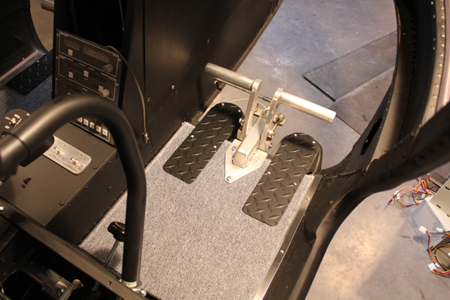
The dual control pedals are constructed of welded 6061 aluminum, have replaceable oil bronze bushings for extended service.
They connect to the computer using a Honeywell SS495 Hall effect sensor for position accuracy.
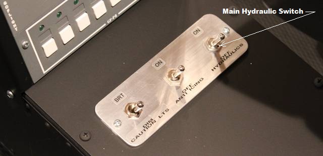
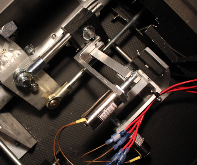
When the main hydraulic switch on the center console is in the "off" position, extra force applied to the cyclic stick is needed, and simulated by using relay driven electromagnet solenoid damping to generate cyclic resistance. The hydraulic circuit breaker in the overhead panel is wired "in line" with the hydraulic switch and can be "pulled" when simulating hydraulic failure emergency procedures.
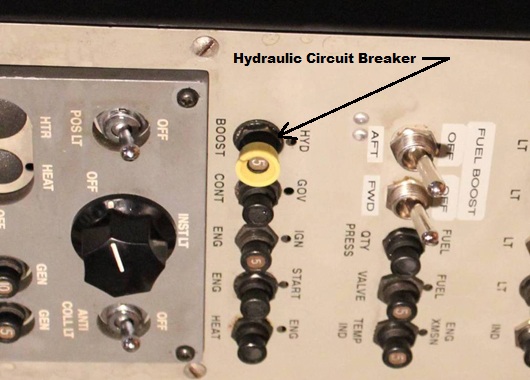
The electromagnet solenoid damping (brake like action) simulates off/on of the real cyclic hydraulic actuator system.
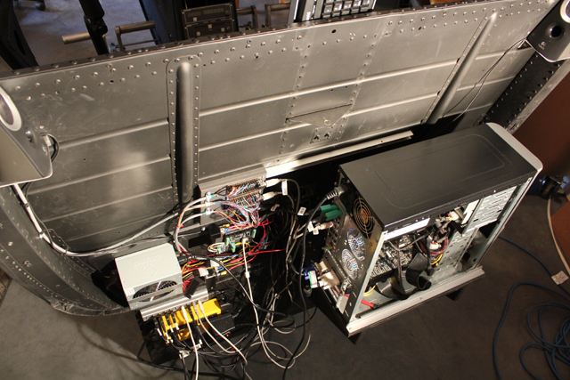
The simulator computer is positioned at the rear of the flight deck.
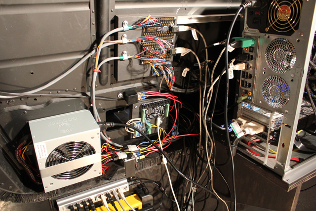
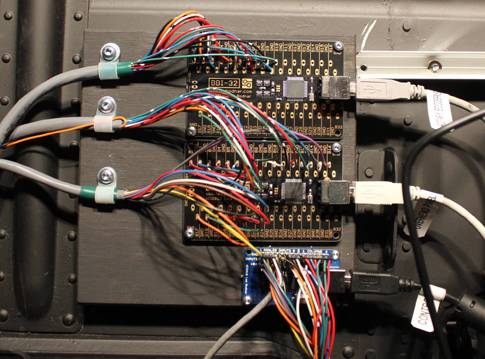
The rotary encoders and switches USB interface boards, and the 12-bit USB joystick controller.
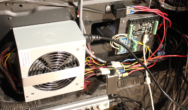
The hydraulics simulation power supply and relay controllers.
![]()