Bell 206 JetRanger Helicopter Simulator
![]()
Bell 206 JetRanger Helicopter Simulator
![]()
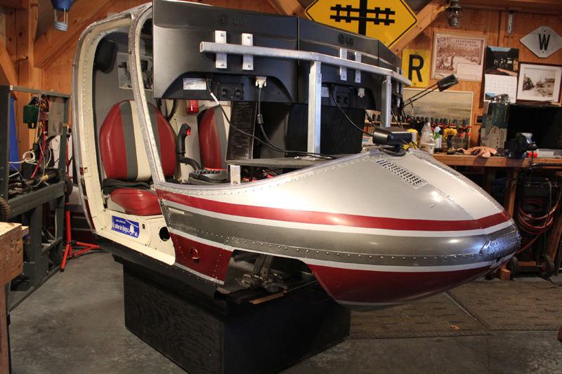
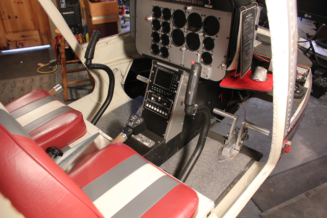
For those that have an interest, I have put together these few pages of pictures to help show the ever changing process of building this helicopter simulator. The Bell 206BII flight deck was salvaged from a roll over accident that had caused some damage to the helicopter's front left side. All of the original flight controls, gauges, instrument panel, doors, seats, and windscreens had already been removed before I acquired the front section of the JetRanger helicopter. The floor pan had also been removed, so 3/4" plywood was used for the base and floor, and to stiffen the flight deck at the back. I fabricated a few aluminum panels for the inner and outer bottom door sills and repaired the left side damage somewhat with fiberglass cloth and resin.
The simulator has all the functioning real buttons and switches needed for a realistic 206 turbine engine start and warm-up, complete with realistic associated sounds, accurate flight characteristics, and shutdown procedures. The simulator can now be used effectively for Bell 206 turbine transition training, as well as general familiarization with helicopter flight and procedures. For the most part this has been made possible by the DodoSim 206 FSX helicopter simulator software from Dodosim Flight Simulation. (www.dodosim.com)
A lot of time has past since this webpage was first started and I continue to refine the flight controls and computer related components. The simulator is used for testing new flight simulator software and hardware, and as a result, I've been able to incorporate my dual-control flight controllers as you will see in the photos below. These days most of my "simulator time" has gone into building flight controls for commercial type simulators as well as other simulator builders, which has left little time for my own. Below is a breakdown and description of some of the components that make up the simulator, hopefully some of the following will be of use to someone just starting out and looking for ideas.
![]()
Display
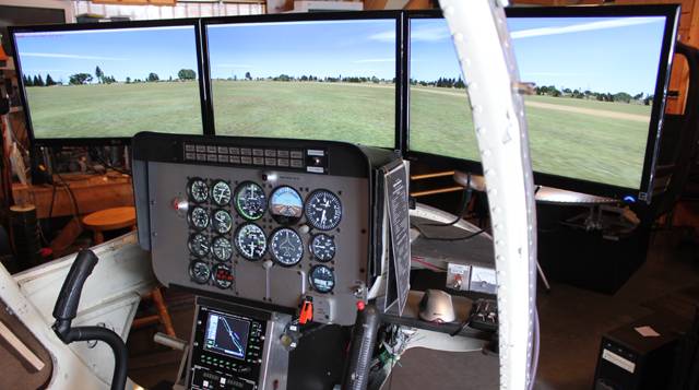
The scenery is displayed by three identical 23" IPS monitors connected to a digital Matrox TripleHead2Go
Gauges and Instruments Panel
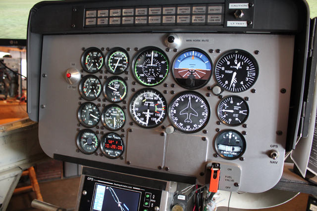
The Bell 206 instrument panel is simple and compact, which makes it convenient to display the gauges from a single LCD monitor .
The panel overlay allows the computer generated gauges and instruments on the LCD to show through.
The black gauge face rings are sections of 2" I.D. and 3" I.D. ABS plastic pipe turned on a lathe and glued to the panel with epoxy. Push button momentary switches have been installed for the TOT light test, warning horn mute, and caution light test. The push button switches are mounted in contoured aluminum rings that have been turned on the lathe to accommodate the length of the switch. The panel has working rotary encoders (rotational knobs) for the altimeter, attitude indicator, and directional gyro instruments. The rotary switches are from GoFlight and are wired to a GoFlight remote RP-48 USB interface. A red metal Bell 206 safety latch is installed on the toggle switch that is used to control the main fuel valve.
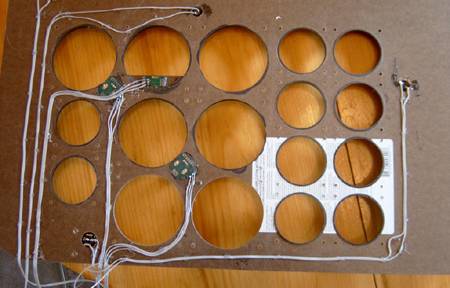
The instrument panel overlay is made from 1/8" thick Masonite and the connecting wires to the switches are strands of ribbon cable that have been hot glued to the back of the board to keep them in place. The rotary and button switches are recessed and "flush" with the surface on the back of the board. The monitor's LCD screen was stripped of all plastic parts, (stand, back, and front bezel) so that the panel overlay would fit as close as possible. Essentially the depth of the wire is the space between the panel and the monitor, about 1/16 of an inch. Although not shown in this photo, 1/16" thick self adhesive foam pads were placed on the back of the overlay panel near the push buttons in order to provide more cushioning and protect the LCD screen.
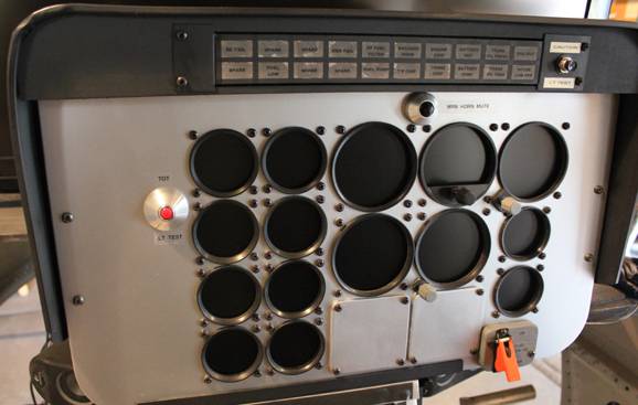
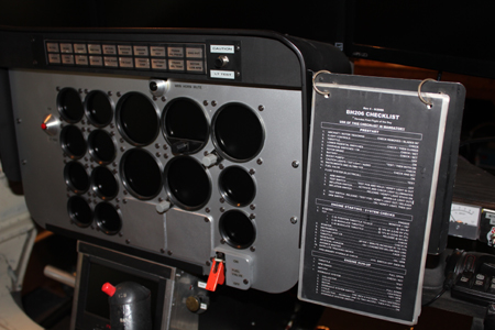
Annunciator Panel
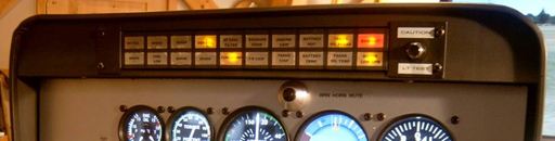
The JetRanger type annunciator warning panel has 20 caution lights and a momentary push button switch to test the lights.
More information on the construction of the annunciator panel can be found here.
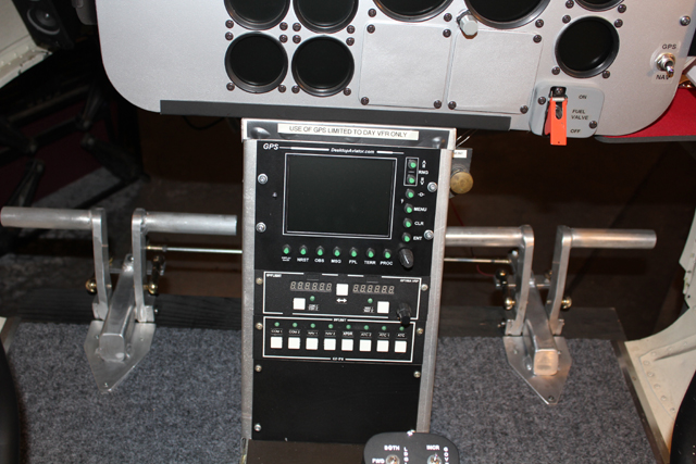
GPS, Radios, Console Switches
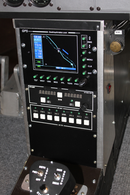
GPS screen is displaying the Reality XP Garmin 530
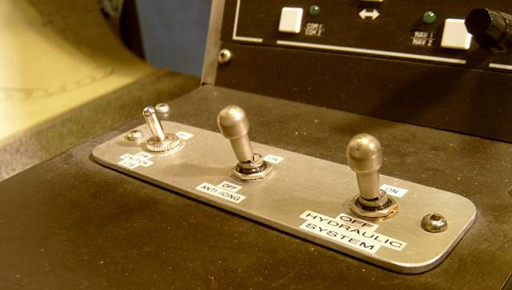
Center console mounted switches for hydraulics, anti-icing, and caution light brightness control.
![]()
Overhead Panel
[ Switches and Circuit Breakers ]
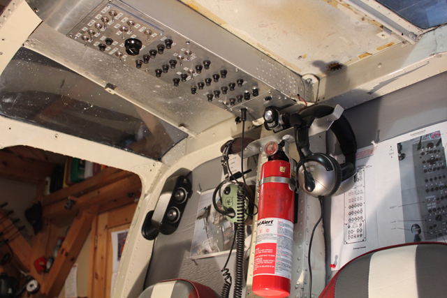
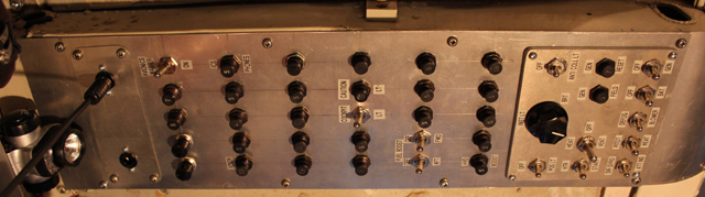
All of the switches needed for startup and flight of the 206 helicopter are operational and function like the real thing. In this case, the circuit breakers will not actually trip (as there is not enough current in the line), but they do act as standard "on-off" switches. For example, the overhead hydraulic circuit breaker is "in line" with the main hydraulic switch, so pulling this breaker gives the same results as flipping the hydraulic switch to the "off" position. This is made possible in FSX by using the Dodosim 206 FSX helicopter software, and FSUIPC4 for switch assignments. Having a breaker "in line" with a circuit will let you do proper emergency procedures for a system failure of that circuit, an important feature for real world helicopter training.
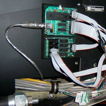
This Plasma-Lite V2 and Ace-4X expansion card handles all of the overhead switch and circuit breaker inputs.
![]()
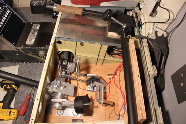
Collective Controller
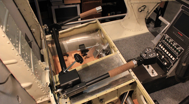
Bell 206 type dual-control collective
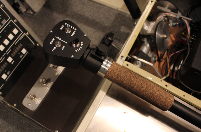
The main collective lever incorporates a twist grip throttle and a spring loaded mechanical idle release button. The throttle grip has a detent position that interacts with the idle release button for realistic simulated Bell 206 startup and shutdown procedures. Accurate turbine engine starts are made possible in FSX with the Dodosim 206 FSX software add-on from Dodosim Flight Simulations. The collective switch head has working starter, governor RPM, and landing light switches. The Dodosim 206 FSX, along with FSUIPC4, allows for the dual landing light switch to operate the dual landing lights correctly.
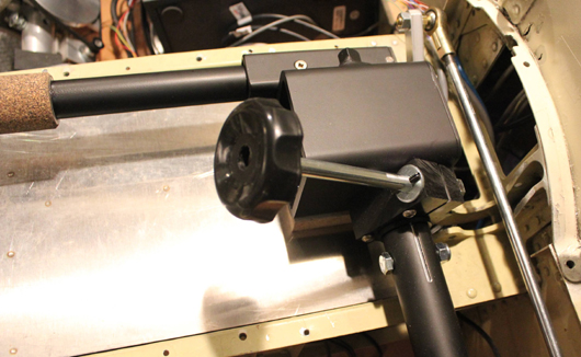
Photo showing collective friction control knob and Delrin friction brake.
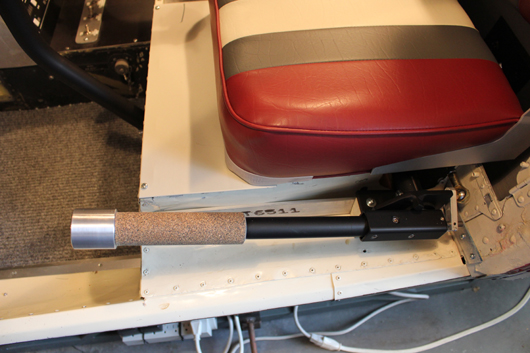
The secondary collective lever is connected to the main collective with a 1 1/4" O.D. aluminum tube.
A 5/16" plated steel rod with adjustable spherical rod ends connects the throttle linkage to each collective lever.
Dual flight controls allow pilot input from either seat.
More information on single and dual control collectives can be found here.
![]()
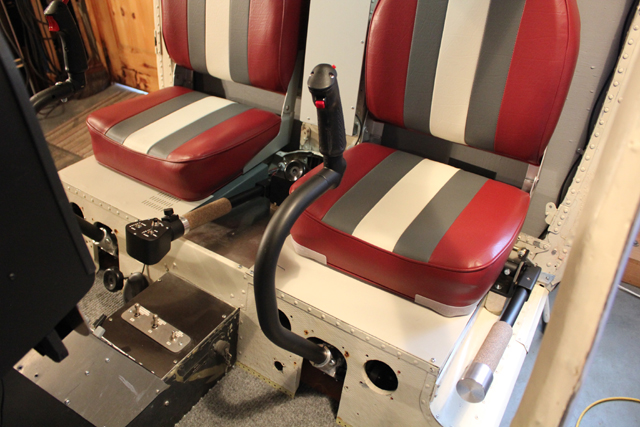
Cyclic Controller
The cyclic sticks are 1 1/4" O.D. tempered aluminum tube.
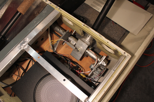
The two cyclic sticks are connected by a 1 5/16" O.D. 6061 aluminum torque tube on the pitch axis,
and a 3/8" plated steel connecting rod on the roll axis.
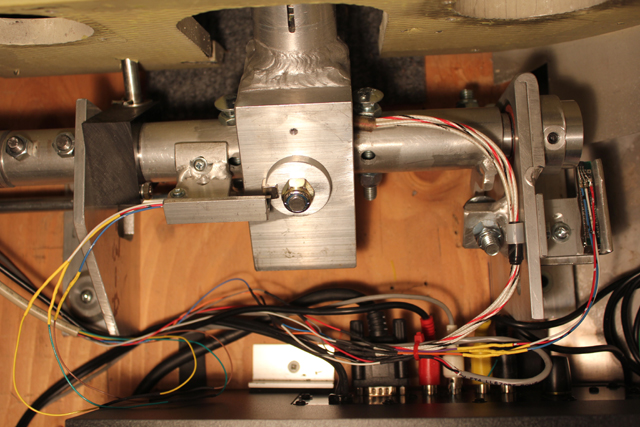
The cyclic base is fabricated from 6061-T6 aluminum and is secured to the floor under the seat enclosure. The cyclic base incorporates ball bearings on each axis for strength and smoothness. Two Honeywell SS495 Hall effect sensors are used to keep track of each axis position and are connected to a 12-bit USB joystick controller.
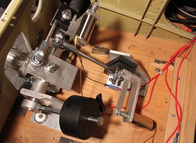
Shown here is the "simulated hydraulic system" on the dual control cyclic torque tube which resides under the left seat base. When the main hydraulic switch on the center console is in the "off" position, extra force applied to the cyclic stick is needed and simulated by using relay driven electromagnet solenoid damping to generate cyclic resistance. The electromagnet solenoids and levers produce a brake like action simulating "off" of the cyclic hydraulic actuator system when 12V power is applied to the solenoids. When the main hydraulic switch is in the "on" position the relay cuts the power to the solenoids and allows the cyclic to move freely as if the hydraulic actuators were working.
More information on single and dual control cyclic controllers can be found here.
![]()
Pedals
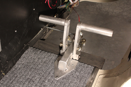
The pedals shown here are made from 6061-T6 aluminum.
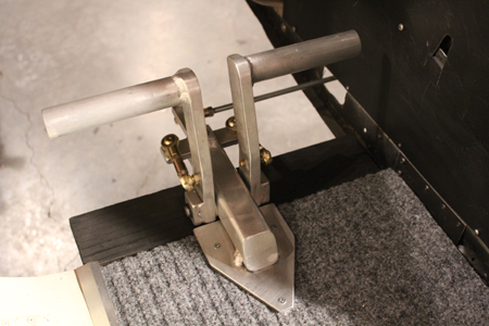
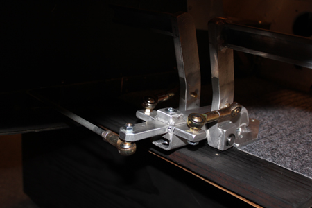
The two pedal sets are connected by a 5/16" plated steel rod with adjustable spherical rod ends.
More information on Bell 206 style pedals can be found here.
![]()
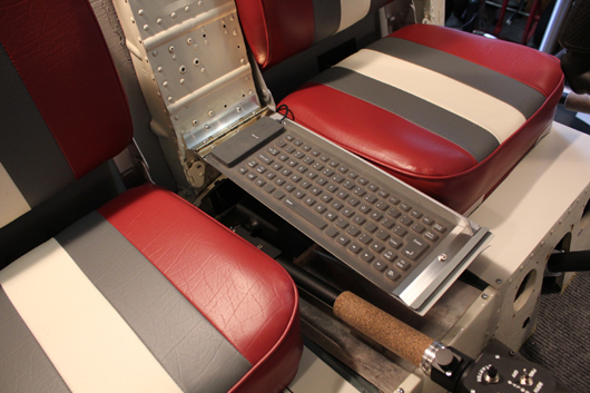
Although it is not specifically needed for flight operations, from time to time a keyboard is necessary to make changes to the computer. Finding a spot in such a confined space is challenging, but the problem was solved with a hinged drop down shelf with the keyboard attached.
The shelf is mounted to the center column between the seats. When not needed, it just folds up and out of the way.
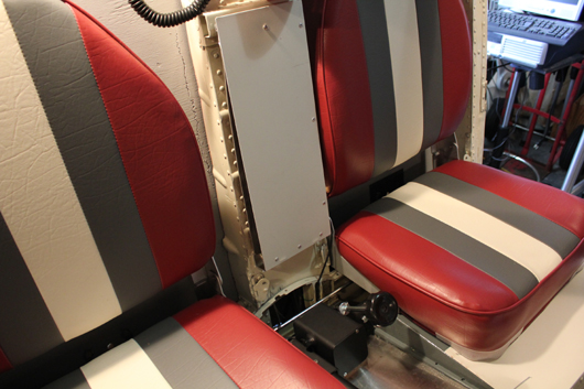
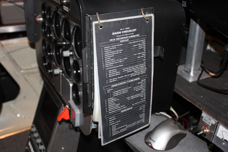
Spring loaded Bell 206 check list and emergency procedures board is located on the right side of the main panel,
and folds out of way when not in use.
![]()
Doors
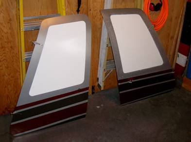
The two doors, one real, one homemade
The real Bell 206 right side door (shown on the right) was salvaged from another wrecked 206. The door was damaged and had to be repaired and painted to match the existing paint. A 1/8" white Masonite panel was used to replace the broken window.
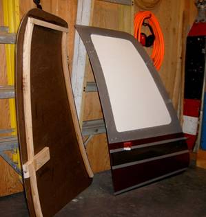
Due to the curves involved, the left side door was fabricated with a piece of 1/8" hard Masonite, bent and glued to oak hardwood strips (precut to shape). A homemade sliding door latch and fabricated Bell type hinges keeps the door in place.
![]()
Reference Pages
Bell 206 Builders Reference Page
Folded Projection System Experiment
![]()
E-mail: jjellen@nrtco.net